Liquid crystal displays (LCDs) are a passive display technology. This means they do not emit light; instead, they use the ambient light in the environment. By manipulating this light, they display images using very little power. This has made LCDs the preferred technology whenever low power consumption and compact size are critical.
Liquid crystal (LC) is an organic substance that has both a liquid form and a crystal molecular structure. In this liquid, the rod-shaped molecules are normally in a parallel array, and an electric field can be used to control the molecules. Most LCDs today use a type of liquid crystal called Twisted Nematic (TN).
LCD Molecules
A Liquid Crystal Display (LCD) consists of two substrates that form a "flat bottle" that contains the liquid crystal mixture. The inside surfaces of the bottle or cell are coated with a polymer that is buffed to align the molecules of liquid crystal. The liquid crystal molecules align on the surfaces in the direction of the buffing. For Twisted Nematic devices, the two surfaces are buffed orthogonal to one another, forming a 90 degree twist from one surface to the other.see figure below.
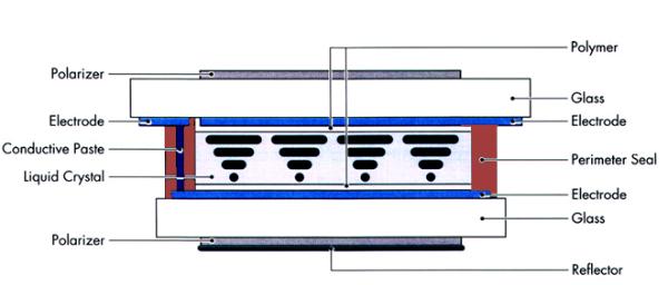
This helical structure has the ability to control light. A polarizer is applied to the front and an analyzer/reflector is applied to the back of the cell. When randomly polarized light passes through the front polarizer it becomes linearly polarized. It then passes through the front glass and is rotated by the liquid crystal molecules and passes through the rear glass. If the analyzer is rotated 90 degrees to the polarizer, the light will pass through the analyzer and be reflected back through the cell. The observer will see the background of the display, which in this case is the silver gray of the reflector.
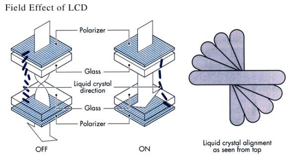
The LCD glass has transparent electrical conductors plated onto each side of the glass in contact with the liquid crystal fluid and they are used as electrodes. These electrodes are made of Indium-Tin Oxide (ITO). When an appropriate drive signal is applied to the cell electrodes, an electric field is set up across the cell. The liquid crystal molecules will rotate in the direction of the electric field. The incoming linearly polarized light passes through the cell unaffected and is absorbed by the rear analyzer. The observer sees a black character on a sliver gray background. When the electric field is turned off, the molecules relax back to their 90 degree twist structure. This is referred to as a positive image, reflective viewing mode. Carrying this basic technology further, an LCD having multiple selectable electrodes and selectively applying voltage to the electrodes, a variety of patterns can be achieved.
Many advances in TN LCDs have been produced. Super Twisted Nematic (STN) Liquid Crystal material offers a higher twist angle (>=200° vs. 90°) that provides higher contrast and a better viewing angle. However, one negative feature is the birefringence effect, which shifts the background color to yellow-green and the character color to blue. This background color can be changed to a gray by using a special filter.
The most recent advance has been the introduction of Film compensated Super Twisted Nematic (FSTN) displays. This adds a retardation film to the STN display that compensates for the color added by the birefringence effect. This allows a black and white display to be produced.
LCD Display Types
Twisted Nematic (TN), Super Twisted Nematic (STN), Film Compensated STN (FSTN), Color STN (CSTN) and Thin Film Transistor(TFT) are the terms used to describe five types of Liquid Crystal Displays, each twisting the orientation of the light passing through the Liquid Crystal Display structure differently to effect contrast and coloration. We also compare coloration, viewing angles, and costs between the technologies.
Twisted Nematic (TN) LCDs
TN displays have a twist (the rotation of the molecules from one plane of the display to the other) of 90 degrees or less. All passive direct drive, active matrix, and most passive low level (x2 to x32) multiplexed LCD's have a 90 degree twist.
The basic Twisted Nematic (TN) LCD consists of a layer of liquid crystal material supported by two glass plates. The liquid crystal material is a mixture of long, cylindrically shaped molecules with different electrical and optical properties, depending on direction.
On the inner surfaces of the glass plates are transparent electrodes, which are patterned to form the desired visual image. The inner surfaces are coated with a polymer, which is rubbed so that the liquid crystal material at one surface lies perpendicular to the other. Across the film of liquid crystal, the molecules form a 90° twist.
On the outer surface of the glass plates, polarizers are placed so they are parallel to the liquid crystal orientation and perpendicular to each other. In the "off" state, light entering the first polarizer is guided by the liquid crystal layer twist to the second polarizer, through which it is transmitted. When the cell is energized, the LC material is aligned with the electric field; light transmitted through the first polarizer is blocked by the second polarizer, forming a dark image. The effect may be reversed if the polarizers are placed parallel to each other, and a light image on a dark background is formed.
The TN technology comes in a single coloration, it is Black characters on a gray background. It is the least expensive, but has the lowest visual quality, primarily in viewing angle.
High Twisted Nematic (HTN) LCDs
HTN (High Twisted Nematic) displays are based on a higher molecular twist (usually 110°) than TN (90°) and therefore offer wider viewing angles and improved contrast. In fact, these HTN products offer viewing characteristics close to those of STN technology. As low operating voltage as 2.5V and marginal extra cost over TN means that the products are well suited to hand-held applications.
Super Twisted Nematic (STN) LCDs
Although Twisted Nematic LCDs may be driven in a time multiplexed fashion to increase the amount of information displayed, they are restricted in terms of reduced contrast and limited viewing angle. To achieve more highly multiplexed displays, super twist technology is employed.
Super Twisted Nematic LCD's have a twist that is greater than 90 but less than 360 degrees. Currently most STN displays are made with a twist between 180 and 270 degrees. The higher twist angles cause steeper threshold curves which put the on and off voltages closer together. The steeper thresholds allow multiplex rates greater than 32 to be achieved.
In this type of display, the LC material undergoes a greater than 90° twist from plate to plate; typical values range from 180 to 270°. The polarizers in this case are not mounted parallel to the LC at the surface but rather at some angle. The cell, therefore, does not work on a light "guiding" principle, as in Twisted Nematic LCDs, but instead on a birefringence principle. The position of the polarizers, the cell thickness, and the birefringence of the LC are carefully chosen to result in a particular color in the "off" state. Usually, this is a yellow-green to maximize the contrast ratio. The LC in the cell is "super twisted" that will give it the ability to use a high multiplex rate. As the twist is increased, the LC molecules in the middle of the layer are aligned with the applied electric field by smaller changes in voltage. This gives rise to a very steep transmission vs. voltage curve, allowing up to 240-line multiplexing.
The STN technology comes in two colorations, Green STN and Silver STN. The STN-Green has Dark Violet / Black characters on a Green background. The STN-Silver has Dark Blue / Black characters on a Silver background. It is in the middle of the road as far as cost, but has very good visual quality. The contrast is similar to TN technology.
Film Compensated Super Twisted Nematic (FSTN) LCDs
The most recent advance has been the introduction of Film compensated Super Twisted Nematic (FSTN) displays. This adds a retardation film to the STN display that compensates for the color added by the birefringence effect. This allows a black and white display to be produced and provides for a higher contrast and wider viewing angle.
The FSTN technology comes in a single coloration, Black characters on a White / Gray background. Of the three technologies listed here, it is the most expensive, but it has better viewing angles and contrast that the STN technology listed above.
Double Super Twisted Nematic (DSTN)
DSTN was the first commercial black and white conversion of the STN display. DSTN displays are actually two distinct STN filled glass cells glued together. The first is a LCD display, the second is a glass cell without electrodes or polarizers filled with LC material for use as a compensator which increases contrast and gives the black on white appearance.
DSTN provides better contrast than STN and FSTN, and offers automatic contrast compensation with temperature. Its response time is significantly enhanced. DSTN reduces the tendency of a screen to be slightly red, green or blue. Since its polarizer mode is negative, DSTN LCDs need backlighting, which is provided by either LED or CCFL only. It provides a resolution up to 122 x 32 dots. DSTN is suitable for use in/with automobiles, gasoline pumps, etc.
Color Super Twisted Nematic (CSTN) LCDs
Color STN Technology is actually STN technology that uses a white backlight and color filters to produce the hues required for a color display. Each visual pixel of a CSTN display is actually physically 3 separate pixels using a colored filter of Red. Green, and Blue. Each of those colors are controlled individually by the graphic controller chip. So in actually; a 320 by 240 pixel CSTN display actually contains 960 by 240 individually colored pixels.
Thin Film Transistor (TFT) LCDs
TFT is a variant of liquid crystal display (LCD) which uses thin-film transistor (TFT) technology to improve image quality (e.g., addressability, contrast). TFT LCD is one type of active matrix LCD, though all LCD-screens are based on TFT active matrix addressing. TFT LCDs are used in television sets, computer monitors, mobile phones, handheld video game systems, personal digital assistants, navigation systems, projectors, etc.
Positive and Negative Display Modes
What types of image the display creates is a cosmetic issue. There are only two basic display modes, positive and negative.
Positive Mode
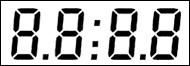 A positive image on an LCD display is opaque when the pixel is "ON", and transparent when the pixel is "OFF". On almost all displays the image is smaller than the background, so this mode of operation is favored in an application where ambient light is high and it will help with the contrast of the display, especially for a display utilizing a Reflective rear polarizer. An example would be a alpha-numeric character on a larger background. The segments or dots on the character would absorb light (appearing dark) and the background (the larger area) would reflect light enhancing the characters. Here are several typical Operational Mode & Viewing Mode combinations and the resulting images (assuming no backlighting which can color the background):
-
TN: Black characters on a Gray background
-
STN-Green: Dark Violet / Black characters on a Green background.
-
STN-Silver: Dark Blue / Black characters on a Silver background
-
FSTN: Black characters on a White / Gray background
Negative Mode
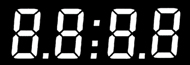 A negative image on an LCD display is opaque when the pixel is "OFF", and transparent when a pixel in "ON". Since the image area is typically smaller than the background, the portion of the display that could reflect light and give the characters definition in this mode is minimized. Therefore, this mode is typically only used when there is a backlight and the ambient lighting conditions are medium to dim. Using a backlight, the transparent segments of the display will "glow" because the backlight will be viewable only when the pixels are turned on. A high ambient light condition could wash out the backlight. Here are several typical Operational Mode & Viewing Mode combinations and the resulting images (assuming a backlight with the specified coloration listed):
-
TN: Glowing Green-Yellow characters on a light Gray background (Green-Yellow Backlight)
-
STN ("Blue-Negative"): Glowing Green-Yellow characters on an light Blue background (Green-Yellow Backlight)
-
FSTN: Glowing White characters on a Black background (White Backlight)
Back to Top
Each LCD has two polarizers, the front and rear polarizers, applied accordingly across the front of the display viewing surface and across the rear of the display to determine how the infuse light into the display. The front polarizer is always transmissive and not selectable by the user, however the rear polarizer has three choices and two grades for each choice.
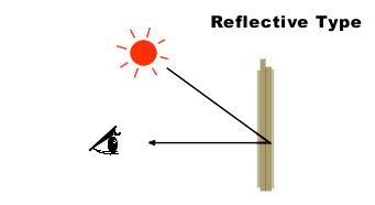
Reflective Polarizer
Reflective displays have an opaque rear polarizer that includes a diffuse reflector, such as brushed aluminum. This layer reflects polarized ambient light that has entered the front of the display back trough the LCD cell. Reflective displays require ambient light to be seen. They exhibit high brightness, excellent contrast, and wide viewing angles. They are particularly suitable for use in battery operated equipment where an adequate level of light is always available. Reflective LCD's cannot be backlit, however they can be front lighted in some applications.
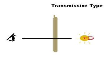
Transmissive Polarizer
Transmissive displays have a clear polarizer on the front and the back. The display therefore depends on light coming through from the back of the display toward the observer in order to be seen. Most, but not all transmissive displays are negative image, and we sometimes add colored filters to different areas of the display to highlight different annunciators. Another example of a transmissive polarizer display would be a transparent window where you could see the segments superimposed over your line of vision through the display window (this assumes a sufficient ambient light source exists on either side of the window).
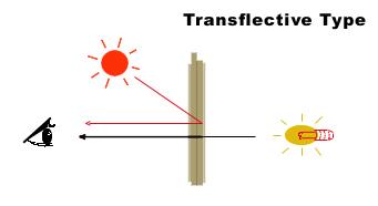
Transflective Polarizer
Transflective displays have a rear polarizer which includes a translucent material which reflects part of the ambient light, and also transmits backlighting. As the name implies, it is a compromise between the transmissive and reflective viewing mode. Used in reflection, it is not as bright and has lower contrast than the reflective type LCD, but it can be backlit for use in low light conditions. This polarizer is the best selection for a display that can be used in all lighting conditions with a backlight.
Commercial Grade Polarizer
The grade of a polarizer determines its operational and storage temperature range. The commercial grade polarizer operates typically between -10°C to +60°C.
Industrial Grade Polarizer
The grade of a polarizer determines its operational and storage temperature range. The industrial grade polarizer operates typically between -30°C to +80°C. Other temperature ranges are also available.
Back to Top
Viewing Direction (Bias Angle)
Viewing direction (or bias angle) is the direction from which the display will look the best. It is set during the manufacturing process, and cannot be changed later by rotating the polarizers. Viewing direction is specified as positions of a clock face. A twelve o'clock viewing direction means that the optimum direction is above the normal to the display, while a part with a six o'clock viewing direction is best viewed from below the normal.
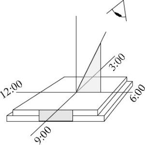
When specifying the viewing direction, one needs to think about how the device is going to be used. For example, a calculator is usually sitting on a desktop or held in the palm of your hand and viewed from the six o'clock direction . Some instrumentation, like a wall thermostat, may be mounted below the viewer and needs to be viewed from the twelve o'clock direction. Other viewing directions are possible but not common. A car clock display, which is usually to the drivers right, may have a nine o'clock viewing direction, or possibly a ten-thirty one if the clock is low on the dashboard.
In a direct drive display, viewing direction is not critical because the display will look good from almost any direction. It becomes critical when the display is multiplexed. The higher the multiplex rate, the greater the problem becomes. In displays with extremely high multiplex rates, great care must be taken when designing the drive circuitry. Special films can also be applied to the front of the display glass to enhance the overall viewability. However they tend to be expensive.
Back to Top
The viewing angle is the angle formed on either side of the viewing direction (or bias angle), where the contrast of the display is still considered acceptable. The term "viewing angle" is often used erroneously with the term "viewing direction" or "bias angle".
Liquid Crystal Displays have a limited viewing angle. They lose contrast and become hard to read at some viewing angles and they have more contrast and are easier to read at others. The size of the viewing angle is determined by several factors, primarily the type of Liquid Crystal Display fluid and the duty cycle. Because the viewing angle tends to be smaller than most people would like, certain viewing direction (or bias angle) is designed into the module at the time it is manufactured. This means the nominal viewing angle is offset from the perpendicular by some amount. Several versions of the LCD module are then offered with this bias set to different angles or positions to accommodate as many applications as possible.
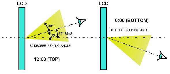
An STN character display running at a duty cycle of 1/16 has a viewing angle of ±20 degrees, and a bias angle of 25 degrees. For this example, assume the display is a 12:00 (top viewing) type. When the display is viewed from 25 degrees above the vertical, it will have its maximum contrast and best “look”. If the viewer moves his eye further above the display by an additional 30 degrees, he will see the display reduce in contrast (but still be easily readable). Moving the viewing position any further above the display will reduce its contrast to an unacceptable degree.
Contrast Adjustment and Viewing Angle
Adjusting the contrast voltage, VO, will effect the viewing direction (bias angle) to some extent, but not the viewing angle. 12:00 display can be optimized for a 6:00 viewing position by adjusting the contrast voltage. A 12:00 display set for 6:00 viewing position will not have as great a contrast as a 6:00 display set for 6:00 viewing position, and vice versa. Designers often want a display to be optimized for straight-on viewing. Either a 12:00 or a 6:00 module can be used; and the contrast voltage can be adjusted slightly to optimize the display for that viewing position. In the example used above, the viewing angles of both the 6:00 and 12:00 modules actually overlap the perpendicular (or straight on) viewing position.
Back to Top
There are three primary methods to connect the LCD with its control circuitry.
Elastomers (Zebra Strips)
Elastomers are silicon strips of alternating conductors and insulators. These materials are generally soft and compliant and can be easily compressed between the Liquid Crystal Display and circuit board. Elastomers require a bezel to squeeze the display and circuit board together. This method will yield a higher conductor interconnection than pins, potentially less costly than pins, but requires a specialized compression bezel.
Pins
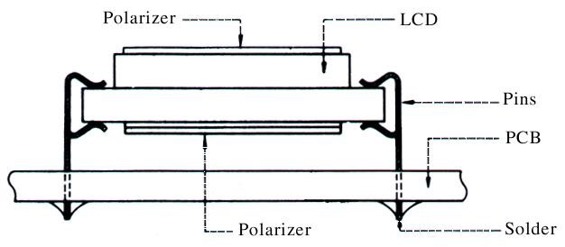
Pins are attached to the display to allow the user to either mount the display in a socket or solder it directly into a circuit board. From an end user standpoint, pins are the easiest to use since there is no requirement for a compression bezel or expensive heat seal bonding equipment.
The pins are attached to the glass with a structural epoxy on the back. On the top, we apply an electrically conductive epoxy with an RTV overcoating. Pins are the most reliable connection method, they are also the easiest to deal with for prototyping and smaller production runs. However, of all three methods, they have the lowest number of interconnects per inch.
Heat Seals
Heat seals are similar to flexible circuit boards with the difference being that the interface tabs are made of a conductive hot melt adhesive. Generally, particles such as carbon, gold, or silver are added to the adhesive to make it conductive. The pads of the heat seal are aligned with the pads of the display and a hot bar is brought down under pressure and the conductive adhesive is melted and bonded to the display. The adhesive is allowed to cool and an electrical bond is made with the display. This method is the most cost effective for the higher volume applications, but due to the expensive setup and equipment required in this process, Heat Seals are typically not used for lower volume / low interconnection density requirements.
Other Types of Connection
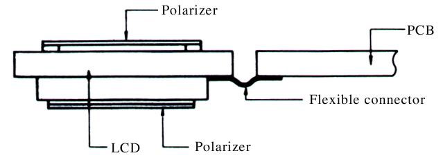
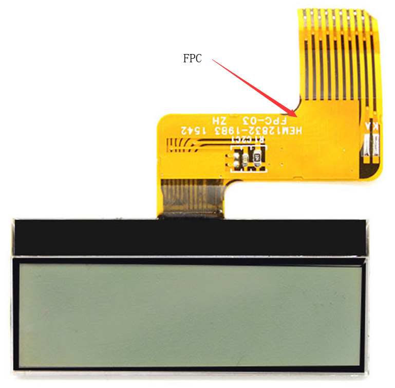
FPC (Flexible Print Circuit) is a circuit substrate of patterning Cu electrode with Polyimide film as a base. Usually offers more flexibility than Flexible Flat Cables.
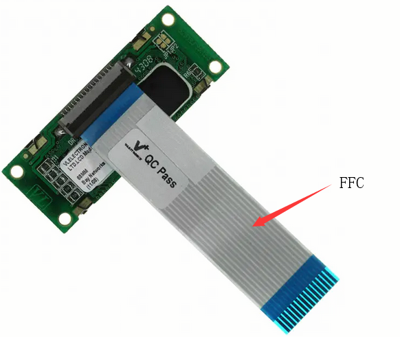
FFC (Flexible Flat Cable) is a cable with two smooth or corrugated, but essentially flat, surfaces. Attached to the PCB by soldering or plugging into a zero insertion force connector. Very reliable.
Back to Top
Light Emitting Diode, or LED, backlight is the most popular backlighting for small and medium LCDs. The advantages of LED backlighting are its low cost, long life, immunity to vibration, low operational voltage, and precise control over its intensity. The main drawback is it does require more power than most of the other methods, and this is a major drawback if the LCD size is large enough. LED backlights come in a variety of colors, with yellow-green being the most common, and now white is becoming cost effective and very popular. LED backlights offer a longer operating life - 50,000 hours minimum - and are brighter than ELPs. Being a solid state device, they are configured to operate with typically a +5VDC power (and optionally 12VDC power), so they do not require an inverter.
The LED backlight has two basic configurations; Array and edge lit. In both types the LEDs are the light source that are focused into a diffuser that distributes the light evenly behind the viewing area. In Array lit configuration there are many LEDs mounted uniformly behind the display, it offers more uniform and brighter lighting and consumes more power. In Edge lit configuration, the LEDs are mounted to on side (typically the top) focused edge on into the diffuser, it offers a thinner package and consumes less power.
Electroluminescence Panel (ELP) Backlighting
Electroluminescence Panel, or ELP, is a solid state phenomenon which uses colored phosphors, not heat, to generate light. EL backlights are very thin, lightweight and provide an even light. They are available in a variety of colors, with white being the most popular for use with LCDs. While their power consumption is fairly low, they require voltages of 100 VAC @ 400Hz. This is supplied by an inverter that converts a 5, 12 or 24 VDC input to the AC output. Information about these inverters can be found in the Power Supply section of our website. ELPs also have a limited life of 3,000 to 5,000 hours to half brightness. The biggest drawbacks to an EL panel is that it requires an inverter to generate the 100VAC, consistent brightness, and limited life.

Cold Cathode Fluorescent Lamp (CCFL) Backlighting
Cold Cathode Fluorescent Lamp, or CCFL, backlights offer low power consumption and a very bright white light. The primary CCFL configuration used in LCD backlighting is edge lighting. A cold cathode fluorescent lamp is the light source with a diffuser distributing the light evenly across the viewing area. CCFLs require an inverter to supply the 270 to 300 VAC @ 35KHz used by the CCFL tube. Information about these inverters can be found in the Power Supply section of our website. They are used primarily in graphic LCDs and have a longer life - 10,000 to 20,000 hours - than ELPs do. Their biggest drawbacks are: cold weather will reduce the light output by as much as 60% (see graph below), they require an inverter to generate the 350VAC (please note that the inverters do not function well at low temperatures), the light intensity cannot be varied (it is either on or off), and vibration can reduce the life expectancy of up to 50%.
Woven Fiber Optic Mesh Backlighting
 Woven Fiber Optic Mesh backlighting provide extremely uniform backlight, without the need for an inverter. The lifetime is dependent on the type of bulb used, with halogen (which generate high heat) or LED sources providing up to 100,000 hours. The bulbs themselves are usually mounted away from the LCD, where they can be easily replaced when necessary. Woven fiber optic panels tend to be somewhat expensive, but the uniformity and brightness are worth the extra cost for some applications. Woven Fiber Optic Mesh backlighting provide extremely uniform backlight, without the need for an inverter. The lifetime is dependent on the type of bulb used, with halogen (which generate high heat) or LED sources providing up to 100,000 hours. The bulbs themselves are usually mounted away from the LCD, where they can be easily replaced when necessary. Woven fiber optic panels tend to be somewhat expensive, but the uniformity and brightness are worth the extra cost for some applications.
Incandescent Backlighting
 Incandescent Lamp backlighting is only used where cost is a major factor. While Incandescent lights are very bright, they are not uniform, generate a significant amount of heat (which can cause problems at high temperatures), have short life spans, and use significant power for the brightness achieved. They can provide very white light, but the color can change with changing supply voltages, and they can be sensitive to shock and vibration. Incandescent Lamp backlighting is only used where cost is a major factor. While Incandescent lights are very bright, they are not uniform, generate a significant amount of heat (which can cause problems at high temperatures), have short life spans, and use significant power for the brightness achieved. They can provide very white light, but the color can change with changing supply voltages, and they can be sensitive to shock and vibration.
|
Back to Top